Line Driver Receiver PCB | MIDIbox
Line Driver Receiver PCB | MIDIbox
Special Price
$8.50
Regular Price
$10.00
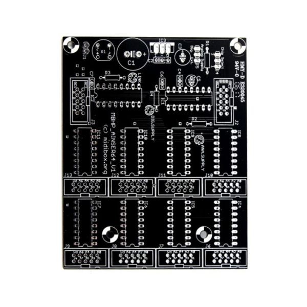
The line driver modules have been designed to connect SPI devices and serial shift registers (DINs/DOUTs) to a MIDIbox over long distances.
This is for a Line Driver Receiver PCB ONLY in a standalone/MIDIbox format.
Availability:In stock
BrandMIDIbox/ ucApps.de

The line driver modules have been designed to connect SPI devices and serial shift registers (DINs/DOUTs) to a MIDIbox over long distances. For this purpose two MC3487 are used as transmitter, and two MC3486 as receiver ICs to transfer the serial signals with bidirectional voltages according to ANSI TIA/EIA-422-B (also known as RS-422). With the given hardware connections up to 5m are possible at 1 MBit/s. Even longer cables could work, but haven't been tested at my side. They might require special twisted pair cables at the right impedance (100 Ohm) - however, the given solution works properly with cheap 25pin male-to-male "parallel cables" as known from the PC world which are also used to connect printers (before the USB era).
Two SPI ports are provided. A SPI port can be used to
- extend serial shift register chains (SRIO) such as MBHP_DIN, MBHP_DOUT and MBHP_DIO_MATRIX
- connect SPI devices such as MBHP_AOUT, MBHP_AOUT_NG, MBHP_AINSER64, MBHP_AINSER8
The first SPI port (J2) is usually connected to the end of the SRIO chain (DIN/DOUT modules) or directly to J8/9 of the core module at the MIDIbox side, and allows to connect additional DIN/DOUT modules at the receiver side.
The second SPI port (J19) is usually connected to J19 of the core module, and to SPI devices at the receiver side.
Note that both SPI ports can handle two devices: a separate DIN and DOUT chain can be connected to J2, and two SPI devices can be connected to J19, because two chip select lines (RC1 and RC2) are available.
Typical Use Cases
Here some wiring examples for typical use cases:

- J8/9 (the SRIO port) of the core module is directly connected to J2 of the transmitter module
- The J2_SI jumper is mounted, so that the J2:SI pin is directly routed to the transmitter port
- J19 of the core module is directly connected to J19 of the transmitter module
- JCI port not used here (they would allow to route two additional input signals through the cable
- a long cable between transmitter and receiver module
- DIN/DOUT modules connected to J2 at the receiver module
- one or two SPI devices connected to J19 of the receiver module
Following diagram shows how DIN/DOUT connections could be extended:

- One or more DINX4/DOUTX4 modules are connected to J8/9 of the core module with a Y cable
- J2 of the MBHP_DOUTX4 module connected to J2 of the transmitter module
- The J2_SI jumper is not mounted! Instead the J2:SI pin of the DINX4 module is connected with a cable to the J2:SI input of the transmitter module
- J19 of the core module is directly connected to J19 of the transmitter module
- JCI port not used here
- a long cable between transmitter and receiver module
- Additional DINX4/DOUTX4 modules connected to J2 of the receiver module, again with a Y cable
- one or two SPI devices connected to J19 of the receiver module
MIDIbox SEQ users will prefer this wiring:

- J8/9 (the SRIO port) of the core module connected to J1 of the MBSEQ Frontpanel PCB
- J2 of the Frontpanel PCB connected to J2 of the transmitter module
- The J2_SI jumper is mounted, so that the J2:SI pin is directly routed to the transmitter port
- J19 of the core module is directly connected to J19 of the transmitter module
- JCI port not used here (it's planned to use these lines for DIN Sync Clock and Start/Stop input in future)
- a long cable between transmitter and receiver module
- DOUTX4 module connected to J2 at the receiver module
This module can output 8 Gates, 8 Clocks (incl. Start/Stop) and 16 additional Gates/Drum Triggers
Note that a second DOUTX4 module could be connected behind this one for +32 additional gates/drum triggers (MBSEQ firmware supports up to 48 gates/drum triggers aside from the "common" gates which correlate to the CV outputs) - a AOUT_NG module connected to the JAOUT port of the receiver module (it has a matching 5-pin layout which is used by AOUT modules)
| Brand | MIDIbox/ ucApps.de |
|---|---|
| Additional Resources | BOM Additional ReadingM |
 -15%
-15%
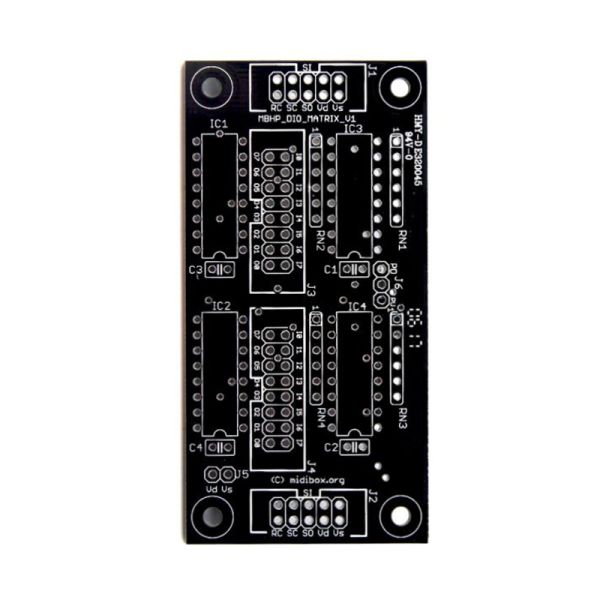
DIO Matrix PCB | MIDIbox
Special Price
$8.50
Regular Price
$10.00
 -15%
-15%
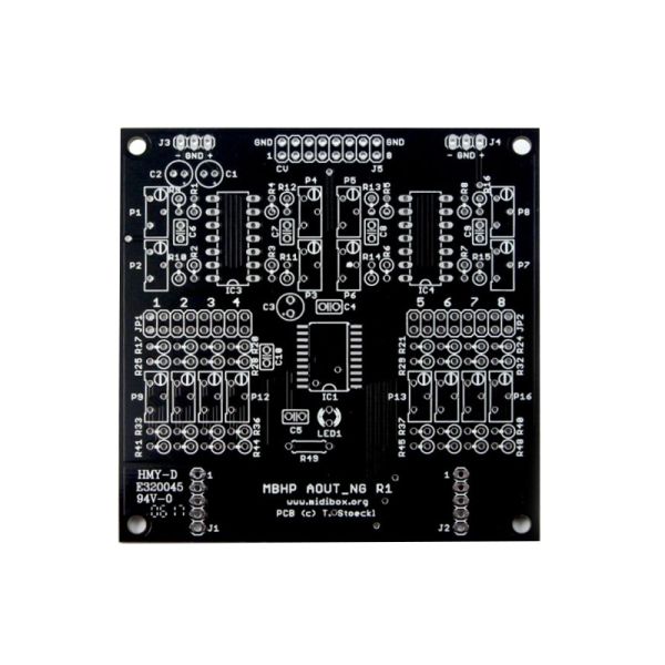
AOUT_NG PCB | MIDIbox
Special Price
$10.20
Regular Price
$12.00
 -15%
-15%
Quad-IIc-MIDI PCB | MIDIbox
Special Price
$10.20
Regular Price
$12.00
 -15%
-15%
MB6582 - SID Synth Main PCB | MIDIbox
Special Price
$25.50
Regular Price
$30.00

MIDI Box/ Waldorf Style Knobs | ALBS
Starting at $1.13
 -15%
-15%
SEQ V4 - Sequencer Control PCB | MIDIbox
Special Price
$34.00
Regular Price
$40.00
 -15%
-15%
Core8 PCB | MIDIbox
Special Price
$8.50
Regular Price
$10.00
 -15%
-15%
MF MotorFader NG PCB | MIDIbox
Special Price
$10.20
Regular Price
$12.00
 -15%
-15%
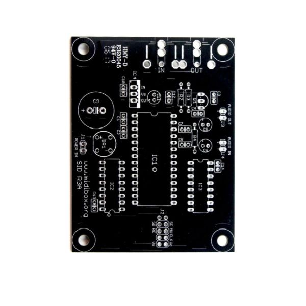
SID Module PCB | MIDIbox
Special Price
$8.50
Regular Price
$10.00
 -15%
-15%
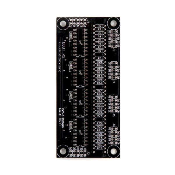
DIGITAL OUT (DOUT) PCB | MIDIbox
Special Price
$8.50
Regular Price
$10.00
 -15%
-15%
MB6582 - SID Synth Control PCB | MIDIbox
Special Price
$25.50
Regular Price
$30.00
 -15%
-15%
AINSER64 PCB | MIDIbox
Special Price
$10.20
Regular Price
$12.00
 -15%
-15%
DIGITAL IN (DIN) R5 PCB | MIDIbox
Special Price
$8.50
Regular Price
$10.00
 -15%
-15%
MIDI I/O PCB | MIDIbox
Special Price
$8.50
Regular Price
$10.00
 -15%
-15%
Core STM32F4 PCB | MIDIbox
Special Price
$10.20
Regular Price
$12.00