MB6582 - SID Synth Main PCB | MIDIbox
- Home
- MB6582 - SID Synth Main PCB | MIDIbox
MB6582 - SID Synth Main PCB | MIDIbox
$30.00
The MB-6582 Base PCB project is based on the MIDIbox SID V2 Hardware Platform (MBHP).
This is for a BASE PCB ONLY in a standalone/MIDIbox format.
Availability:In stock
BrandMIDIbox/ ucApps.de
MIDIbox SID V2 Bassline Demo #5 from Thorsten Klose on Vimeo.
Base PCB
-
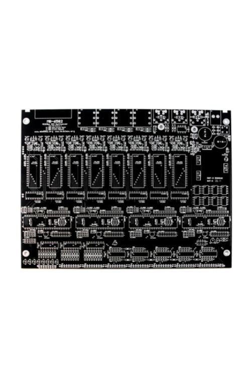
The base PCB is essentially a merging of multiple MIDIbox modules into one compact PCB, and should work exactly the same as connecting multiple MIDIbox modules with cables. Almost all the ports on the Core module are available, with identical pinouts.
-
The base PCB can be stuffed with (at most) 4x PIC18F4685, 8x SID, 8x 24LC512, 5x 74HC165 (40 digital inputs) 3x 74HC595 (24 digital outputs).
-
The base PCB has 9v and 12v supply rails which you can connect to a pair of SIDs, so each pair of SIDs can be either 6581 SIDs or 8580/6582 SIDs.
-
You don't have to use all the SID sockets. You can use from 1 to 8 SIDs. You can choose to put SIDs in stereo pairs, or only put a SID in the left SID socket for a mono channel.
-
You don't have to use all the PIC sockets. You can choose to use less than four PICs.
-
You don't have to use the DIN/DOUT at the bottom of the PCB, and you don't have to use the optimized switch/LED matrix I designed to get a “step C” control surface with only 8 shift registers, and you don't have to use a “step C” control surface (or any control surface). However, TK has kindly done all the code changes to support the optimized switch/LED matrix so you can have a big control surface with only the shift registers on this PCB.
-
The base PCB is exactly 9200mil x 7215mil (9.2 inches x 7.215 inches). This fits exactly into the PT-10 case by PacTec, with mount holes that line up with the case standoffs.
There are four different ways of supplying power to the base PCB:
PSU Option A: C64 power supply, generating only 9v supply (no 12v) … exactly like the prototype, it converts the 9v AC coming from the C64 power supply. This option only allows use of SIDs that need 9v (8580 or 6582), the 6581 needs 12v. One 9v voltage regulator is used to supply 9v to all the SIDs.
PSU Option B: C64 power supply, generating 9v and 12v supply … almost exactly like the "C64 PSU Optimized" circuit, which adds the 9v DC to the 5v DC to create 14v DC, enough to get the 12v required for 6581 SIDs. Instead of a voltage regulator on each SID module, there are just two (one 9v and one 12v).
PSU Option C: Uses 5v regulation circuit to provide option A or B when not using C64 PSU (which has its own 5V regulation). I have added this option at the last minute to the PCB as a potential workaround for people unable to get a C64 PSU. People could generate 5v from a single unregulated 9v AC supply (9v AC adapter) or supply separate unregulated 9v AC and unregulated 5v DC supplies (9v and 5v AC adapters), using the same power socket and switch. Please do not assume this idea will work well, it might introduce noise, hum and heat!
PSU Option D: External regulated power supply circuit, supplying +12v,+9v,+5v and ground … for those people wanting to use their own power supply, because they don't want to use the C64 PSU.
| Brand | MIDIbox/ ucApps.de |
|---|---|
| Additional Resources | BOM Schematic Wilba's Build Guide |


