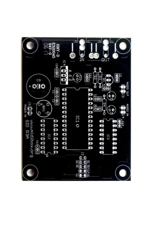
SID Module PCB | MIDIbox
- Home
- SID Module PCB | MIDIbox
SID Module PCB | MIDIbox
$10.00
The SID module has been designed in a way which allows to stack CORE and SID module, so that both boards don't require much more place than a cigarette packet (just for the case that you plan to use multiple modules for a stereo or quattro SID system
This is for a PCB ONLY in a standalone/MIDIbox format.
Availability:In stock
BrandMIDIbox/ ucApps.de
MIDIbox SID is a non-commercial & "DIY-only" project. Beside of the common SID functions (three oscillators, triangle/saw/pulse/noise and mixed waveforms, independent envelope generators for the amplitudes, sync & ringmodulation, 12db multistate low/band/highpass/notch filter) it features four different software based synthesizer engine implementations:
The module requires a second power supply which delivers clean and stable 12V for the audio section of the 6581 chip. The current drain is below 100 mA, so the smaller "lite"-version of the 7812, the 78L12 can be optionally used as voltage regulator. If you plan to utilise a 8580 instead of the 6581, 9V are required instead - so replace the 78L12 by a 78L09 (or 7809...) in that case. Note that the original C=64 power supply unit can be used for the SID module, although it only delivers 9V AC - the 5V DC which is are also delivered this PSU shifts the voltage to 14V (see schematics below). If you don't want to use the C64 PSU, you can power both modules with the same transformer or wallwart for both modules. 14-15V AC (!!!before!!! the regulation unit) are required for a good and noiseless sound.
The SID has to be clocked at 1 MHz. As clock source the PWM output of the PIC has to be used (Core::J7:SO/PIC Pin #17). The usage of the oscillator found in older pictures is not recommended anymore, since it can lead to problems (details are described in this forum article).
Note that only the redesigned layout of the MBHP_SID module provides a terminal for this connection. If you've built a module based on the _v2 layout, you need to solder an additional cable between the CLK input of the SID and Core::J7:SO/PIC Pin #17.
An Audio Out and In can be found on the module. The function of the small transistor behind the SID Output isn't to amplify the signal, but to save the SID chip from any damage - so, never bypass this protection! If you are not able to find a BC547, just take any other "general purpose NPN" transistor - take care for the pinning! The SID also provides an Audio IN which allows external audio signals to be mixed with the SID output and to be processed through the 12db multimode filter.
The two caps between Pin 1/2 and 3/4 of the SID are required for the filter. The ideal values may differ with the SID version you are using, so it's possibly a good idea not only to purchase the recommended 470 pF caps for 6581, 22nF caps for 8580 (which have been taken from the original schematics), but also some other pairs: 1nF, 2.2nF, 4.7nF, 6.8nF - just to check for any better results.
The printed circuit board has been designed in a way which allows to stack CORE and SID module, so that both boards don't require much more place than a cigarette packet (just for the case that you plan to use multiple modules for a stereo or quattro SID system :)
If you are interested: here an Interview with Bob Yannes who created the SID chip 20 years ago and later co-founded the synthesizer company Ensoniq can be found.
| Brand | MIDIbox/ ucApps.de |
|---|---|
| Additional Resources | BOM Schematic Additional Reading Continued Reading |
