It's 555... v5 - Pulse Divider PCB | NonLinear Circuits
It's 555... v5 - Pulse Divider PCB | NonLinear Circuits
$25.00
This module takes an input signal and splits it into clusters of 5 independent pulses. Each pulse can have its width modulated by pot or CV and can be set to any amplitude or even inverted.
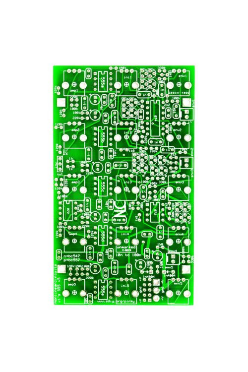
This is for a PCB only, suitable for the Eurorack format.
Availability:In stock
BrandNonLinear Circuits
This is a set of five 555 based one shot circuits. Each has CV and pot controlled pulse width and the pulse for each can be set up by pot to be negative going or positive at any desired amplitude, or off when the pot is set to the center. The circuit is supposed to be driven by a signal from a VCO. This enables the creation of five pulses that can be individually manipulated to create a complex and harmonically rich waveform. A slower clock signal will give clicks and glitches (A voltage controlled glitch module….you are lucky).
As the pulse-widths can be individually controlled (or controlled en masse by “CV all”), this waveform can be continually can be continually morphed to get new sounds. When the 5 pulses are quite thin the effect is similar to that of a resonator. The controls allow a wide range of pulse width (0-100%) so fatter, thicker sounds can also be created. Depending upon the pot settings, this module will oscillate without any input. This means it can be used as a voltage controlled noise source and a voltage controlled drone module. Some settings of the “init1” pot will stop this oscillation and lock up the module. Connecting a signal from a VCO to the input will get it cycling again.
The current version allows all stages to have the 0-100% range. To use this module is simple, connect the output (inverted or regular) to a mixer and have a listen. Tweak the pots to hear how the sounds change. Connect LFO or other CV signals to some of the CV inputs and listen some more. The “env1-5” pots control the effect of CV signals. The “init1-5” pots set the pulse widths. The “amp1-5” pots set the amplitude of the pulses from-5V to +5V, so at the midpoint the pulse will be zero, effectively off. Connect a signal from a VCO to the main input, control the VCO with a CV signal and listen to the output of the “it’s 555…”. It will track the VCO very nicely.
| Brand | NonLinear Circuits |
|---|---|
| Additional Resources | Build Notes & BOM |