CGS87-8 - 8 Step Programmer/Sequencer PCB Set | Cat Girl Synth


CGS87-8 - 8 Step Programmer/Sequencer PCB Set | Cat Girl Synth
$25.00
The Programmer/Sequencer is a Serge inspired multi-stage sequencer.
This is a PCB only suitable for multiple formats
Note: This is a PCB set that contains one CGS87 PCB and one CGS87S PCB
Availability:Out of stock
BrandCat Girl Synth (CGS)
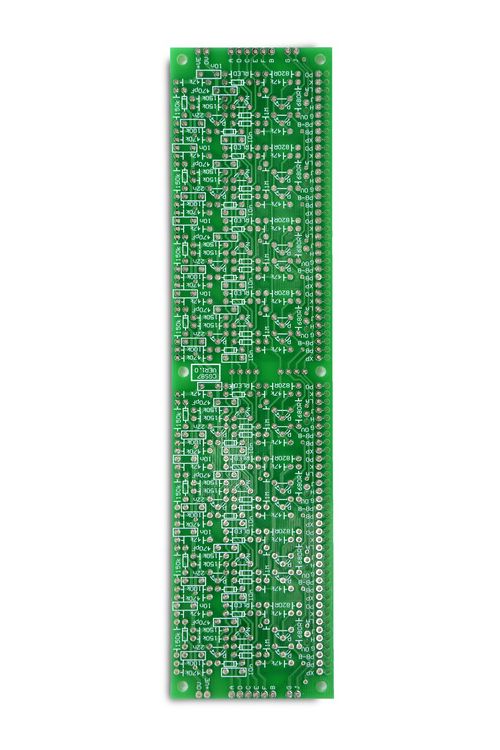
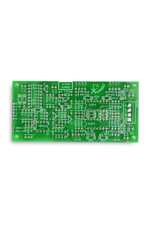
This is a redesigned circuit board for the CGS59 Programmer/Sequencer. Unlike that version, this one has no panel-format specific PCBs. The master PCB still exists, though is somewhat different in structure. The output amplifiers have also been made using TL074 instead of TL072 chips. The column boards have been replaced with boards that contain 8 stages. Pots and their mix resistors can be mounted on something like the CGS94 pot carrier if you want 1" horzontal spacing, or simply panel mounted and hand wired as was traditionally done.
The Programmer/Sequencer is a Serge inpired multi-stage sequencer. Unlike most sequencers, this one makes no use of binary counters. Rather, it uses a set of individual stages, each one directly accessible. As such it could be considered to allow "random access". The first sequencer produced by Serge was a 4017 based counter that put out gate pulses. In order to get a control voltage sequencer, the gate outputs were fed to the input stages of a multi-state programmer. Usually built in groups of four, but sometimes coupled through a switch, these programmers would only allow a single stage to be active at any time, outputting the corresponding control voltages to their bussed output jacks. The stages could be selected either via a gate/trigger input or a panel mounted push button.
This module replicates the programmer, but with one major exception - up and down inputs allow it to be sequenced without connection to an external gate source. Any stage can be activated at any time by a direct pulse or button press. Up or down pulses will then step it from that stage. To limit the number of steps in the sequence, the pulse (gate) output of a stage is simply routed to the external pulse input for the first stage of the sequence. Note that the first stage used in a sequence need not be the first stage on the panel. For example it would be possible to have the first few stages used as an "introduction", with the sequence automatically looping to a stage in the middle of the panel once the sequence's first run was completed.
There is also no theoretical limit to the number of stages that can be used, and I do know of sequencers that have been built with 16 stages. The maximum number of stages is of course chosen prior to building. The astute will recognise the circuits as having grown from that published in the Synapse article. Make no mistake - it wasn't simply copied. Hundreds of hours of R&D and numerous prototypes were needed to get it right, as the circuit has been taken far beyond its original intentions.
A little on how it works:

| The schematic for the CGS87S Programmer/Sequencer interface PCB. Only one of these is needed per programmer/sequencer. |

| The schematic of a single stage of the CGS87 Programmer/Sequencer main PCB. Each of these board contains enough stages for eight steps. They can be cascaded for a greater number of steps. |

| The schematic of the interboard wiring and pot array. Extra CGS87 boards can be added. G and J on the right side of the first PCB are wired to the G and J on the left side of the next, with the final pair looping back to the first G and J. The CGS87S can be wired to either end of the CGS87. |
When looking at the PCB with the pads facing down, as per the photos and diagrams here, the LEFT end of the PCB is stage 1. This is fine if you work on the rear of your panels with the panel flipped top to bottom. If you wish to reverse the sequence order, simply use all UP connections as down, and all DOWN connections as up.
Bus"C" is the output of a current source. This source is capable of holding only one stage on at a time. When a second stage is triggered, it deprives the currently latched stage of current, causing it to reset. In doing so, it removes its load from the current source, allowing the recently triggered stage to remain on.
The up-down function is provided by a dedicated pulse generator in each stage. Only when that stage is active are the pulse generators enabled. Upon receiving an up or down pulse from the corresponding bus, either the next or previous stage will be sent a trigger pulse.
- CPO - Common Pulse Out. (original Serge name. A better name would be 'Button Gate Out') Goes high and remains high while a push button is pushed.
- AEP - All Event Pulse. Gives a trigger pulse on any change of stage.
| Brand | Cat Girl Synth (CGS) |
|---|---|
| Additional Resources | BOM & More Information |