CGS51 - Weighted Random Switch | Cat Girl Synth


CGS51 - Weighted Random Switch | Cat Girl Synth
$15.00
The weighted random switch is another Ken Stone / Cat Girl Synth module for introducing unpredictability into synthesizers.
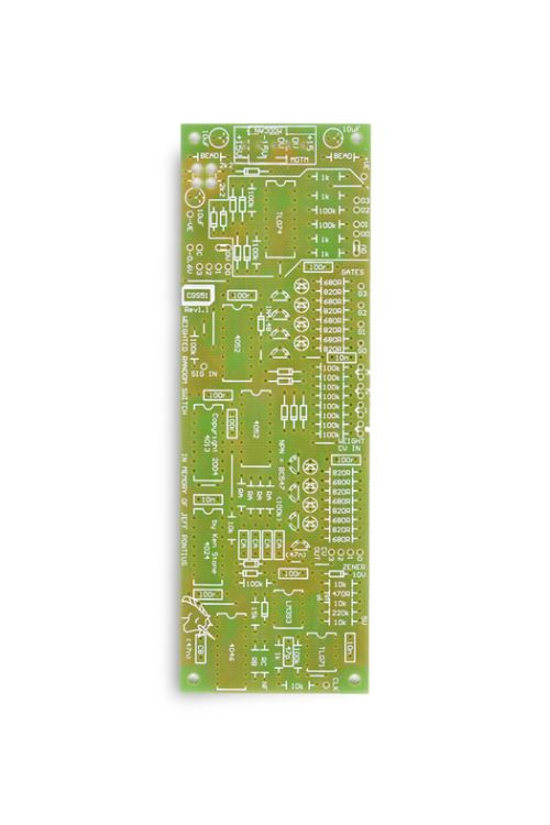
This is a PCB only suitable for multiple formats
Availability:In stock
BrandCat Girl Synth (CGS)
The weighted random switch is another module for introducing unpredictability into synthesizers. The original requirement was for a circuit that would, upon receiving a clock signal, randomly direct a single input to one of four outputs, but with a twist. Four knobs or control voltages could be used to sway the likelihood of one or more outputs being selected over the others.
The concept has been expanded to include four gate outputs that correspond to the selected output, as well as a derived probability output CV for each of the four channels. What distinguishes these outputs from the input probability voltages is that they are post-multiplexer, and thus are interactive. Any change in any weighting control voltage, and all four of these outputs will be affected. They will be an approximation of the input voltage, and subject to some degree of fluctuation at the rate of the internal clock, though this can be adjusted to the users preference at construction time - thus the reason why no resistor or capacitor values have been specified in the buffer circuits.
The circuit is also designed to be expanded by the addition of one or more Analog Switch Matrixes, allowing it to be used to route one input to four outputs, or vice versa, or even to route one signal through one of four external effects (e.g. wave multipliers, filters etc.).
The analog switch is DC coupled so can be used for both control voltages and audio signals, as is the minimal router in the basic version.
A little on how it works:

The schematic of the Weighted Random Switch.(View full sized.)

The schematic of the onboard routing switch.

Power rail connections
The four weighted inputs, be they fed from external CVs or pots, are scanned by a 4 to 1 analog multiplexer (1A) at a high rate. The selected voltage is inverted and limited between 0 and 10 volts, then fed to a comparator (see below) and a VCO. The VCO's frequency is thus inversely proportional to the selected voltage - the higher the voltage, the slower the VCO. Thus the selected input voltage directly controls the amount of time it is selected - the lower the voltage, the shorter that input will be selected - the higher the voltage, the longer that input will be selected. While how long an input is selected has little effect on how this portion of the circuit works, it is the method by which the weighting is generated.
The address lines that are used to select the input CVs are fed via a latch to a second 4 to 1 analog multiplexer. Unlike the first, this multiplexer remains in a fixed stated until an external clock pulse is received via the CLK input (from a sequencer, rhythm unit, LFO etc.). When a clock pulse is received, the current address of the first multiplexer is latched. The chance of any particular address being latched is related to the length of time that particular input is being selected, as caused via the weighting voltages as described above. There are other factors involved too, such as relative clock rates, but these effects can be ignored in most circumstances.
There is an over-ride condition where an external clock pulse is ignored. If one of the weight determining CVs is below around 0.5 volts, it is deemed to be effectively zero - in other words, an unwanted state. The comparator detects this condition and blocks the clock pulse, so the second multiplexer holds the previous state. This may mess up the perceived weighing of that particular state, but it is preferable to selecting a state to which nothing is connected, thus the unit can be used to switch between 2, 3 or 4 different inputs as required.
One part of the second multiplexer (2B) is used to drive the gate outputs and the LEDs that show which output is active. The other part (2A) is either wired as a 1 to 4 signal router with direct connection o the panel jacks, OR as a driver for controlling the more complex Analog Switch Matrix.
The second part of the first multiplexer (1B) is used to drive the weighted CV outputs. These CVs are a bit "soggy" in their responses, and never reach zero. Theoretically when summed the result should always be the same. Thus if one increases, the other three will each decrease by a third of the increase. The LEDs give a vaguely fading indication of the result - useful in its own way, but very different to most LED displays seen in synthesizers. If desired the entire buffer/LED driver section associated with IB can simply be left out.
| Brand | Cat Girl Synth (CGS) |
|---|---|
| Additional Resources | BOM & More Information |