570 Galore - Dynamics Processor PCB/Panel | Timo Rozendal


570 Galore - Dynamics Processor PCB/Panel | Timo Rozendal
$17.00
The 570 Gallore circuit was put together via Timo Rozendal with heavy influence from Thomas Henry's circuit literature.
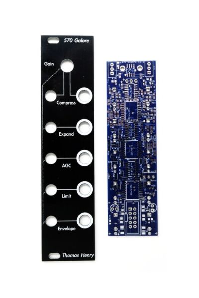
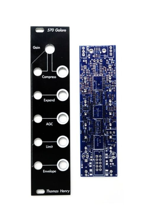
This is for a PCB/Panel in Eurorack Format
Availability:In stock
BrandTimo Rozendal
Story
"I bought a bunch of Thomas Henry books from Magic Smoke and I got really curious about the circuits in the 'Making music with the NE570 compander' book. I decided to make a compact module with as much as I could fit from the book. And then the 570 Galore was born: 5 separate dynamic functions that are normalled to the first input (only the first input has a gain control, if you need more than you need to change the levels with other modules). It features a Compressor, Expander, AGC (automatic gain control, some sort of compressor), Limiter and an Envelop Follower).
It is a tight build, only for the experienced builders and putting it together will be a little puzzle, but it is a fun and versatile module packed with sound shaping tools (and the envelope follower is also very good), especially for drums!
This is not a hi-fi project, but the functions it performs can be still be useful. Be aware that when you have noise in your system a module like this can highlight the noisefloor.
There is not much to tweak so it is possible that for some materials it doesn’t sound good (changing levels already makes a big difference).
Here is a demo
Acquiring the book is recommended for understanding, tweaking and debugging.
I have permission from Thomas Henry to sell this project.
There are 2 versions of the chip: 570 and 571. The 571 is said to be lower specced, but I think for this project it doesn’t matter so much which one you choose (I built them with both the 570 and the 571 and didn’t hear a noticable difference)."
Assembly
Solder these first (ordered from top to bottom):
C1c (1µF), R4 (27k)
R10 (27k)
C4a (2.2µF)
R6L (100Ω)
C2f (2.2µF)
R24 (27kΩ)
R11f (100kΩ)
The reason for this is that they are between the ics (and one half under a trimpot) and very hard to get to if you don’t do them first.
The following smd parts are on the top side:
C1,C2,C3,C5,C6,C7,C8,C9,C10 (all 100nf) and Cda (560pF)
Maybe the best moment to do this is when you are done with all the smd on the bottom side.
| Brand | Timo Rozendal |
|---|---|
| HP | 6 |
| Additional Resources | BOM & Build Info Quick NE571 Source |

9mm Round Shaft (6.35mm) Vertical Potentiometers
Starting at $1.25
 Out of Stock