BMC046 - Digital Noise Source PCB | Barton Musical Circuits
BMC046 - Digital Noise Source PCB | Barton Musical Circuits
$15.00
This module is a PIC based noise source for your DIY modular. It's capable of a wide variety of sounds while using only a couple of simple controls.
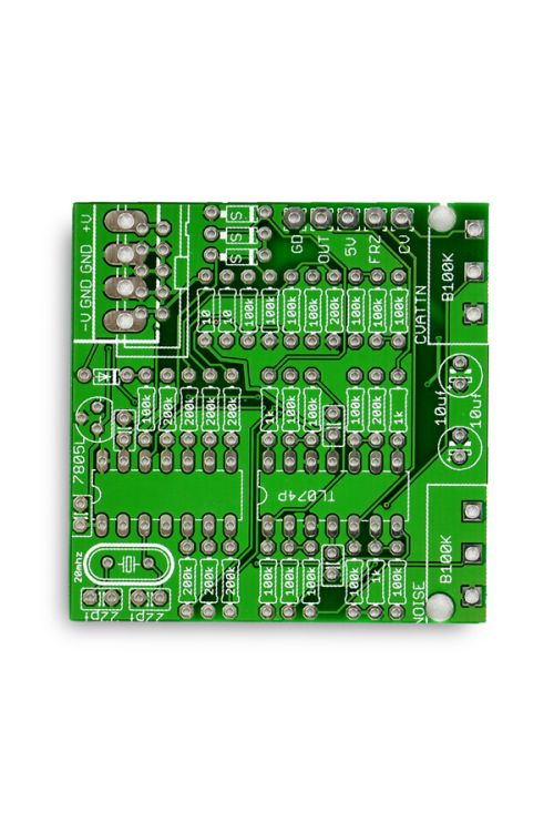
This is a PCB only (including programmed PIC) suitable for multiple formats.
Availability:In stock

This module is a microcontroller based digital noise generator. A program on the microcontroller generates semi-random numbers based on user input, and then outputs these numbers to a Digital-To-Analog converter which results in noise.
The basic program is laid out in the diagram to the right, with all numbers represented as 8-bit binary numbers. The “input number” is determined by the position of the control knob, with fully counter clockwise being “00000000” and fully clockwise being “11111111.”
So, a starting number is “rotated” to the left, meaning that all of the bits move one spot to the left, so the “1” that was at the right end of the number, is now one over, and a zero has replaced it. Whenever this happens, the program checks to see if a “1” has rotated to the left out of the number, if a 1 hasn't rotated out, the rotated number becomes the new starting number.
Whenever this happens, an Exclusive OR (XOR) operation is performed comparing the recently rotated number with the input number, and the result is the new starting number. In addition to providing an input number, the control knob also determines the bit depth of the output. The diagram to the left demonstrates bit depth. The program checks a certain bit of the output number and then makes all bits less significant (the bits to the right) either a 1 or 0 depending on the state of that bit. The bit depth is decreased as the knob is moved clockwise. Having a lower bit depth will result in a louder more distorted sounding noise.
Controls/Inputs/Outputs
- Control Knob – The control knob sets the input number and bit depth for the module. It is marked “Noise” on the PCB
- CV Knob – This knob attenuates the CV input. The attenuated voltage is then mixed with the voltage from the control knob. This is marked “CVATTN” on the PCB
- CV Input – This is the jack for external CV. The wirepad is marked “CV” on the PCB
- Freeze Input – When a positive voltage is input to this jack the output of the module is updated with new voltages. It is normalized to +5V, so the module works when nothing is plugged into it. This can be used to either augment the sound of the noise being generated, or for extracting random steady voltages from the module. It's like the track input of a Track and Hold module. The wirepad is marked “FRZ” on the PCB. 5.Output – This is the DC voltage output. It ranges from 0 to +5V. The wirepad is marked “OUT”
| Brand | Barton Musical Instruments |
|---|---|
| Additional Resources | Build Guide |