BMC004 - VC Clock/Divider PCB | Barton Musical Circuits

BMC004 - VC Clock/Divider PCB | Barton Musical Circuits
$24.00
This circuit generates a clock signal output and up to six additional outputs whose frequencies are divided by the master clock. There is an option for PWM on each of the divided clock outputs which sacrifices two of the outputs (4 divded outputs instead of 6). There are also options for random division and division of external clocks.
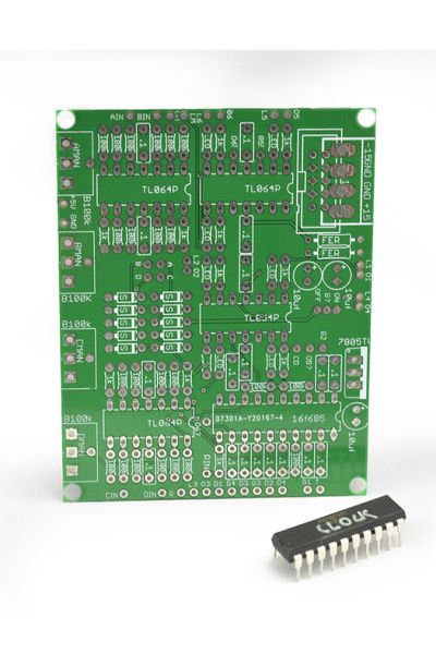
This is for a PCB (including programmed microcontroller) only suitable for multiple formats.
Availability:In stock
The Barton VC Clock/Divider has the following:
Controls:
- TEMPO - The TEMPO control is an analog control. When the DIVIDER control is disengaged (see next section) the TEMPO control determines the frequency of the master clock which the dividers derive their frequencies from. When the DIVIDER control is disengaged, the tempo control is unused.
- DIVIDER- This is a digital control, best implemented as a switch. When set off, the module acts as a master clock, and the RESET control acts as a reset. When set on, the module acts as a divider of an external clock and the RESET control acts as an input for an external clock.
- RESET - This is a digital control, best implemented as a jack for external signals. When the module is acting as a master clock, a trigger or gate signal inputted to RESET will cause the master clock to reset, turning the internal counter back to zero and turning on all outputs. When the module is acting as a divider for external clocks the RESET is used as the input for the external clocks.
- DIVISION1 through DIVISION6 - These are analog controls. In standard operation these select the level of frequency division used for each corresponding output. The levels of division available are 1, 2, 3, 4 , 5, 6, 7, 8, 16, 32, 64. In random operation DIVISION1 through DIVISION4 controls are repurposed and DIVISION5 and DIVISION6 are not used.
- PWM1 through PWM4 - These are analog controls. Each of these controls the pulse width of the corresponding output.
- RANDOM - This is a digital control. When set off, the module acts in it's normal mode. When set on, the module acts in random mode.
Modes:
STANDARD CLOCK/DIVIDER MODE
In standard mode, the modules outputs pulses whose frequencies are divided by a master frequency. In clock mode, this frequency is controlled by the TEMPO control, and in divider mode this frequency is controlled by the clock inputted to the RESET input. In clock mode a rising edge on the RESET input will reset the clock and dividers, setting all outputs high. Pulse width is varied by the PWM controls for each output (not available if using 6 outputs). (Note: when changing divisions in any mode, new divisions are not recognized until after the output goes low, so when dealing with very high levels of division, there may be some delay when changing divisions) GRAPH 1.
RANDOM CLOCK/DIVIDER MODE
In random mode, PWM, RESET and TEMPO controls act identically as they did during standard mode, but the division of frequencies is no longer controlled by the DIVISION controls. Instead, frequency division is randomly selected and the DIVISION controls now control how often the division is selected and what levels of division are available. Each output has a re-roll counter which when it reaches zero causes that output to find a new random division. In Random clock mode, a trigger signal on the RESET input will cause new random divisions are reset all re-roll counters.
- DIVISION1 now controls the re-roll counters lengths. The lengths available are 1, 2, 3, 4, 5, 6, 7, 8, 16, 32, and 64.
- DIVISION2 now controls the input for the re-roll counters. When the analog voltage inputted is less then 2.5 volts each re-roll counter's input comes from it's corresponding output, thus each output's division will change at times which are not directly related to each other. When the analog voltage inputted to DIVISION2 is greater than 2.5 volts, each re-roll counter's input comes from the master clock frequency. This way division changes will sync up with one another.
- DIVISION3 when set above 2.5 volts will allow only divisions which are square of two (2,4,8,16,32,64) to be selected.
- DIVISION4 sets the maximum random division level.
| Brand | Barton Musical Instruments |
|---|---|
| Additional Resources | Build Guide |