BMC044 - 4 Knob Sequencer PCB | Barton Musical Circuits
BMC044 - 4 Knob Sequencer PCB | Barton Musical Circuits
Special Price
$11.25
Regular Price
$15.00
This is a sequencer which uses the position of four knobs to determine all voltages and gate on/off settings for a sequence of up to 32 steps.
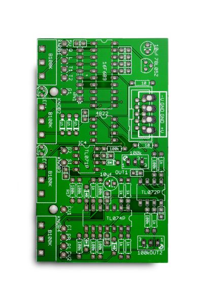
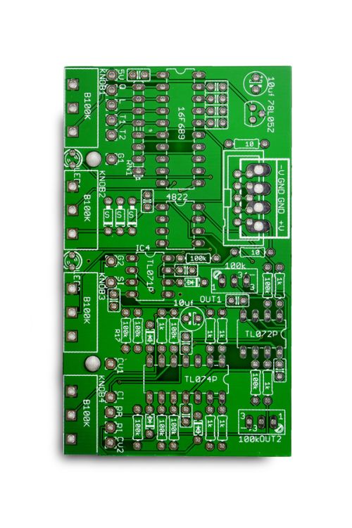
This is a PCB only (including programmed PIC) suitable for multiple formats.
Availability:In stock
The design goal when making the 4 Knob was to generate lots of output from a very minimal amount of input and control. The initial prototype only consisted of a clock input and the 4 knobs as input/control but was able to output two voiced 32 step sequences. More controls were added to either filter this output or help it work in sequence with other parts of a modular system.
The way the sequencer works is that it reads the positions of the four knobs and converts these positions into numbers. It then uses these numbers to determine the number of steps in a sequence (2 to 32 is step range) and what each of the four outputs of the sequence should be doing on each of those steps. Each step has a specific set of instructions, like “Add knob 1 to knob 3 and use that number for the output of Voltage 1. Then check if the third bit of knob 4 is on, if so turn on Gate 2.” This means that the sequences are not random, though the changes are difficult to predict.
CONTROLS
- Knobs – The namesake of the module, each knob's position plays several roles in determining the sequence.
- Quantize Toggle – This quantizes the voltage outputs so that each only outputs voltages in 1/12V intervals.
- Length Toggle – This sets the length to 4, 8, 16 or 32 depending on how you've calibrated your sequencer. See calibration instructions at the end of this document.
- Trigger Toggles – These toggles set the Gate outputs to Trigger mode instead, so that a short pulse at the start of a new step is sent instead of a pulse that remains on throughout the step.
- Reset Button – This tells the sequencer that on the next clock input it should go back to the first step.
INPUTS
All inputs are for timing purposes, they can be used with the outputs of LFOs/VCOs/Clock Generators/Gate/Trigger signals. They all react when the input goes above zero volts.
- Clock – This tells the sequencer when to move to the next step.
- Reset – This tells the sequencer that on the next clock input to go back to the first step. This is useful for synchronizing with other sequencers or putting a hard limit on the length of a sequence.
- Sample – Whenever this is above zero volts, the positions of the knobs are being read. This jack is normalized to +5V so the knobs are read when nothing is plugged in. This allows for sequences to be changed at regular intervals
OUTPUTS
- Voltage – Each of these outputs a DC voltage in the range of 0V and 5.333V, the voltage will change on each step of the sequence.
- Gate – Each of these outputs a +5V pulse on certain steps of the sequence.
| Brand | Barton Musical Instruments |
|---|---|
| Additional Resources | Build Guide |