DE-06 – Nødsignal Broken Tape Simulator PCB Panel Set | DJUPVIKS ELEKTRONIK
- Home
- Module Type
- DE-06 – Nødsignal Broken Tape Simulator PCB Panel Set | DJUPVIKS ELEKTRONIK
DE-06 – Nødsignal Broken Tape Simulator PCB Panel Set | DJUPVIKS ELEKTRONIK
Special Price
$42.50
Regular Price
$50.00
NÖDSIGNAL is a 6hp true stereo broken tape machine simulator.
Availability:In stock
BrandDjupviks Elektronik
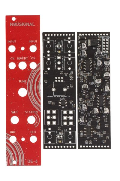
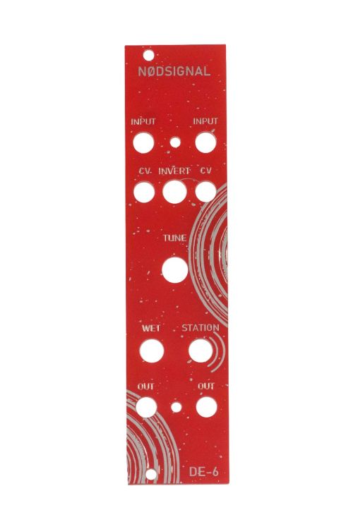
NÖDSIGNAL is a 6hp true stereo broken tape machine simulator. As such it is capable of doing vibrato, chorus as well as ring mod(ish) sounds with the right modulation. Input on channel one (left) as well as CV for the same channel is normalled to channel two (to the right). This means you can get a stereo signal out from just a mono input if you prefer, and you can modulate both channels with just the single cv input. The invert switch inverts the incoming CV signal on channel one before it reaches channel two, creating the opposite of what is modulating channel 1. The dry wet switch removes the dry input when pushed down. Traditionally chorus is done with the dry present and with faster modulation, whereas vibrato is done without the dry input and slower modulation. You can experiment with this, even doing fast cv on one channel and slow on the other. The Station switch presents 2 different kinds of tape saturation, most notable with the wet signal present. The second mode is an envelope follower of sorts which is shown by the white LEDs tracking the signal.The tune knob, with no CV present at the inputs acts as a ”tuner”, skipping the tape around when turned. With a CV signal at the input it works as a attenuator for both CV inputs. At maximum setting (full CV) it also acts as a soft bypass for the wet signal.
Building is straight up and easy. I usually start with the power connector. Then the headers, usually I do female headers on the component board and male on the jack/pot board. Follow the silkscreen to get the pins on the correct side of each board. I solder this by inserting the header and only solder a middle pin. Then putting together the two boards like a sandwich and carefully solder the rest of the pads. One pitfall here is if you decide to remove the boards before you solder all pins the pin might be stuck in the solder joint and dislocate it self from the surrounding plastic. If you want to to this make sure the heat the solder joint(s) before separating the boards.
I do the jacks and pots board next. Fit everything, the jacks and pots and white LEDs. Solder in one pad on each part, the ground pin on the jacks for instance (the one pointing away from the jack that has a square pad), one pin on the pot. Put in the LEDs into the holes (short leg to the square pad) but don’t solder them in. Attach the panel and make the LED’speep out from beneath the panel. Attach some (or all nuts) on pots and jacks. When everything is aligned and looking good you need to go through the PCB and solder every pad on the jacks and the jacks. I usually do the LEDs last after checking once more they look good from the panel side. Dubbelcheck the solder joints on all headers and power connector so there are no shorts or missed pads. Make sure that the boards are connected correctly before turning on the power, that up on jack board faces up on component board.
| Brand | Djupviks Elektronik |
|---|---|
| HP | 6 |
| Additional Resources | Build Guide |


