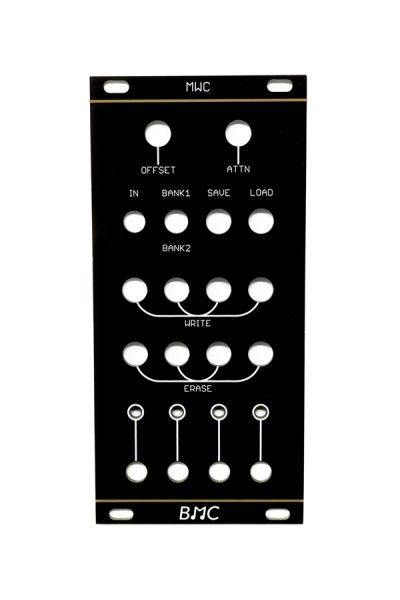
BMC008 - Multi-Window Comparator | Barton Musical Circuits
BMC008 - Multi-Window Comparator | Barton Musical Circuits
From $11.25 Regular Price $15.00
To $67.50 Regular Price $90.00
This circuit is a new type of comparator. A microcontroller checks the input voltage against a data table that tells it whether to turn it's output on or off. This is repeated 4 times for 4 different outputs. The data tables are written by the user using pushbuttons or external trigger/gate sources.
Availability: In stock


A window comparator is a circuit with three inputs and 1 output. The first two inputs are an upper voltage threshold and a lower voltage threshold. If the third input is inbetween these two thresholds, it turns the output on, and if it is not, the output turns off.
A Multi-Window comparator, like the "regular" window comparator has an input voltage and an output that toggles on or off depending on the input voltage. The difference is that instead of comparing the voltage to two other voltages, instead the voltage is converted to a number and that number is looked up on a data table which says to either turn on or turn off the output at that voltage. This gives the user the chance to create lots of windows, so that multiple voltages and ranges of voltage can trigger the same output. This project is 4 multi-window comparators which share a single input voltage, each comparator has it's own look-up table.
INPUTS:
- Voltage input - This is the voltage that is telling the microcontroller where to look on the data tables. This input corresponds to all four outputs.
- External Write/Erase inputs (optional)- A trigger or gate signal can be inputted to the module to perform write/erase commands to the tables. You would need these inputs duplicated for each channel
OUTPUTS:
- Channel Outputs - There are four of these. These output +5V whenever the input voltage is in an "on" window for that outputs look-up table.
CONTROLS:
- Input Attenuator - This attenuates the input signal. The microcontroller only recognizes voltages between 0 and 5V, so this reduces large signals so that the full signal can be read by the microcontroller.
- Input Offset - This adds a voltage offset of between 0 and 5v to the input signal. When using an input signal that may be negative part of the time (like an LFO) this can bring the negative parts of the signal into the proper range for the micro controller's input. This can also be used as a manual control voltage when not using an input signal.
- Write/Erase Buttons - These should be non-latching push buttons, there is a write button and an erase button for each of the 4 channels. When the write button is engaged, the data table will be told to turn on at the current input voltage. When the erase button is engaged, the data table will be told to turn off at the current input voltage.
- Bank Select switch - This should be a SPDT center off type toggle switch. There are two databanks for saving your lookup tables. When this switch is turned either up or down it tells the microcon to save or load from the up or down bank. When the switch is in center position, it disables saving or loading from EEPROM. You should leave the switch in the center position normally, so you don't accidentally save or load a table.
- Save/Load Buttons - These should be non-latching push buttons. The save button will save the current 4 data tables to the selected memory bank when pressed. The load button will load the 4 data tables in the selected memory bank and begin using them. When an erase button is held down on a channel and the load button is pressed at the same time, it will erase all "on" windows in that channel.
| Brand | Barton Musical Instruments |
|---|---|
| HP | 12 |
| Additional Resources | Build Guide |

Davies 1900H Style Knobs | Modular Addict
Starting at $0.56
 Out of Stock
16PJ138 Style 3.5mm Jacks (Bag of 50)
Special Price
$11.25
Regular Price
$15.00