Analog Logic Gates | Low-Gain Electronics


Analog Logic Gates | Low-Gain Electronics
From $30.00
To $124.50
A flexible bank of four “analog” logic gates!
Availability: In stock
BrandLow-Gain Electronics
*PCB error: Somehow the trace from the +12V source wasn’t drawn to the 78L06 input pin. The 6V regulator feeds the LM3900 for the Schmitt Triggers. You can easily fix this by jumping the 12V over to pin 3 of the 78L06 (input pin). Use wire or a resistor lead just be careful of shorting.
The Analog Logic Gates module is bank of 4 Logic Gates and 4 Schmitt Triggers. You might ask yourself why they’re called “analog” when it utilizes a digital CMOS chip to do the gates…
The simple answer is that the inputs to the logic gates are all conditioned with comparators capable of accepting any analog signals within the modular system. That means you can feed an
oscillator, trigger, gate, envelope, lfo, etc into the inputs and it will still automatically convert the signal to an appropriate signal for the logic gate to process. Any voltage presented at the inputs
over roughly 1V will register as a logic HIGH. So “analog” is mostly stating that this is not just a “digital logic” module that can only be used with other “digital logic” modules. You can process any
signals you want to generate Digital output signals. You could think of them as “analog to digital converters (ADC)”
Which Logic Gates the module has is set by which CD4000 series Logic Chip is chosen:
CD4011/4093 (NAND),
CD4001 (NOR),
CD4071 (OR),
CD4081 (AND),
CD4030/4070 (XOR),
CD4077 (XNOR)
The bank of 4 logic gates are set by the chip, in a quad package configuration, so you can’t mix and max Logic Gates within this one bank of four.
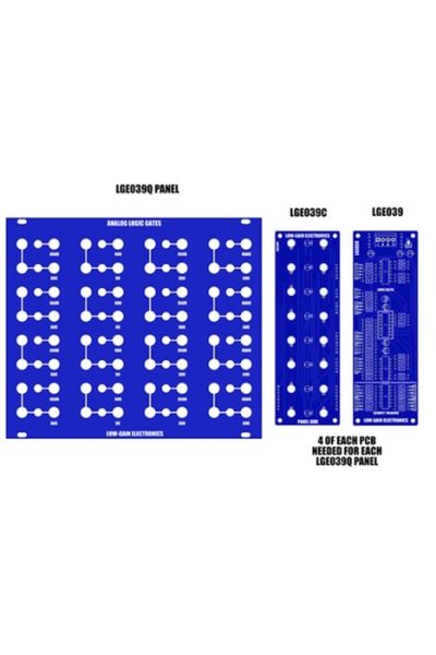
However, Should you chose to use the panel I have made available, you can set up a large Logic Gate Bank of 4 modules behind one panel giving you 2 banks of AND, 1 bank of OR, and 1 bank of XOR gates
The “NOT” outputs or “inverted” logic gate outputs on the panel shown are generated using the 4 Schmitt triggers. Simply run the Logic Gate output into the Schmitt Trigger Input to generate an inverted (NOT) output of that Logic Gate
You can wire the Schmitt Triggers to the panel by using banana jacks instead of wiring the inputs behind the panel which would give you the option of running anything you want through them. It’s your choice
| Brand | Low-Gain Electronics |
|---|---|
| Additional Resources | Build Guide |