Digital Filter Simulator | NonLinear Circuits
Digital Filter Simulator | NonLinear Circuits
As low as $18.70 Regular Price $22.00
Digital Filter Simulator This module is based on ideas presented in a 1969 IEEE paper titled - Hybrid Implementation for Sampled-data controllers.
Availability: In stock
BrandNonLinear Circuits
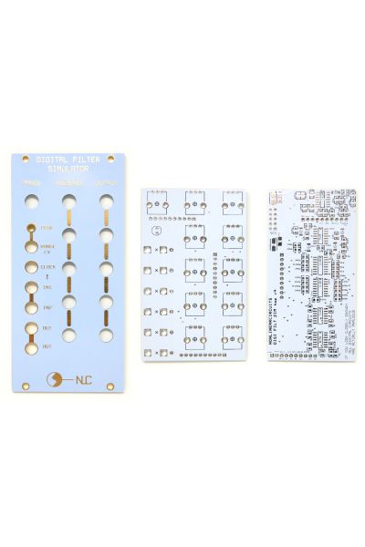
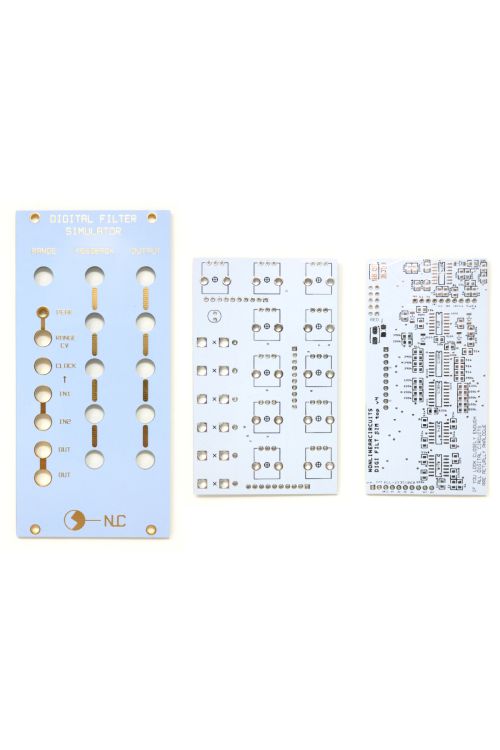

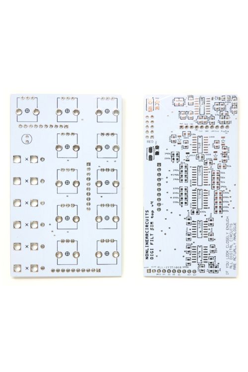
Digital Filter Simulator This module is based on ideas presented in a 1969 IEEE paper titled - Hybrid Implementation for Sampled-data controllers. The paper presents the canonical form of a generalised digital filter made using analogue elements…..yes this is an analogue circuit; all CMOS and op amps. I played around with various versions for a few years and, as usual, settled on the simplest and cheapest version.
Incoming audio signals (or CV if you want to use it as a pattern generator) are fed to a 4 bit A/D stage, these 4 bits then go thru a 4 stage delay (shift registers). Each delayed bit is re-united with its siblings via four D/A stages and the stepped signals are then fed back to the input via an attenuator/inverter stage and are fed to the summed output, again via an attenuator/inverter stage.
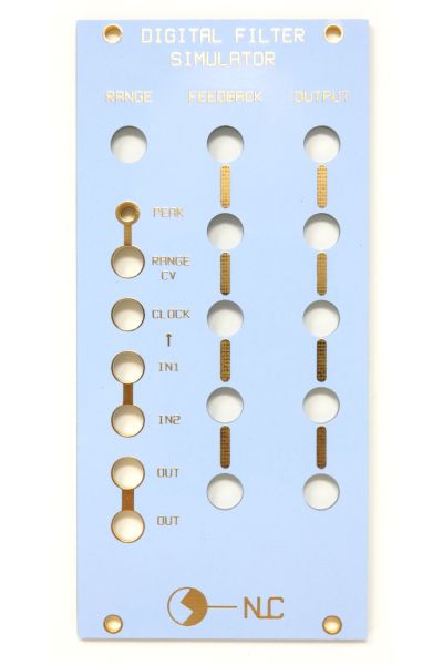
The circuit is controlled by the clock input that ticks over the shift registers. CV controlling the VCO that supplies the clock signal will in turn control the filter. The Range pot needs to be set to a suitable level, I like it when the peak LED is flickering. Range can also be controlled by CV which will allow you to shift from a 1 bit signal to a 4 bit or overdrive the crap out of it and lock everything up. It is interesting to supply clock signals that are multiples or divisions of the audio signal, but like all NLC modules, feel free to do whatever you like. As mentioned, supplied with a gate and a CV it will perform as a complex pattern generator as well.
| Brand | NonLinear Circuits |
|---|---|
| HP | 12 |
| Additional Resources | BOM & Build Guide |
 -25%
-25%
P518M "Thonkiconn"-style Inline 3.5mm Jacks (Bag of 50)
Special Price
$11.25
Regular Price
$15.00

9mm Round Shaft (6.35mm) Vertical Potentiometers
Starting at $0.94

Davies 1900H Style Translucent Knobs | Modular Addict
Starting at $0.56

Davies 1900H Style Knobs | Modular Addict
Starting at $0.56

9mm T18 Shaft Vertical Potentiometers
Starting at $0.75
 Out of Stock
16PJ138 Style 3.5mm Jacks (Bag of 50)
Special Price
$11.25
Regular Price
$15.00