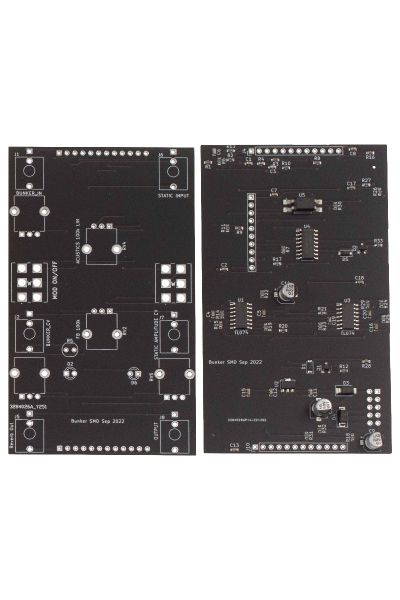
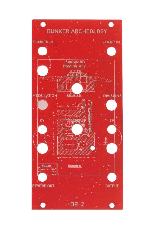
DE-02 – Bunker Archeology Digital Reverb Tank PCB Panel Set | DJUPVIKS ELEKTRONIK
DE-02 – Bunker Archeology Digital Reverb Tank PCB Panel Set | DJUPVIKS ELEKTRONIK
$85.00
Bunker Archeology is the world’s first ”bunker simulator” composed by two different sections: an overdriven digital reverb “tank” as well as frequency driven tremolo/VCA1. The module is normalized so the incoming signal is first sent to the reverb tank and then to the static (tremolo) circuit. The latter could also be used as a crude (albeit backwards) VCA. However one can easily patch it the other way around by inserting an incoming signal to the “Static in” and patching “Output” to “Bunker In”.
Availability:In stock
BrandDjupviks Elektronik
Using “Bunker Input” you can attenuate the incoming signal, this is helpful since the reverb tank is pushed to its very limits2. Depending on how you attenuate the incoming signal (also of course depending on how “hot” the incoming signal is, digital oscillators for instance tend to be a lot hotter) the module will behave differently, not just in regards of distortion3. You can regard the whole circuit as a bastardized envelope follower of sorts (that being said placing a VCA before the input is usually a fun idea, or any modulation of frequency really). When the modulation switch is switched on (ie. Downwards) it causes the reverb tank to gradually shut down (or attacking itself), shorting out the tank using a LDR and a LED. This creates interference and noise which is sent to the static circuit. It can be used for drones (shaped with the acoustics knob) or percussive sounds. The modulation knob lets you dial in the amount and character of that sound and how much of the tank that should be shorted. This knob also has CV control (expecting 0 to 5V and ignoring negative voltages). “Acoustics” knob lets you change the overall acoustics of the bunker which in turn effects how static behaves (since the static circuit is frequency driven, altering the frequency changes overall behavior of the static circuits speed and/or stuttering). Feedback is the amount of signal being fed back into the reverb tank4. “Reverb Out” is a dedicated output for the reverb section and can be used for mixing downstream in your rack for those times you don’t want the static interference, just a grainy lo-fi reverb). You can also use an external mixer to combine the two outputs. Plugging in a cable into the “Reverb Out” will not stop sending the reverb signal to the static circuit.
“Static in” is a dedicated input for the static circuit. Plugging in a cable here will remove the reverb from the static circuit completely (but still present at the reverb out, as described above). “Divisions” switch determines the overall speed of the static circuit. There are three different options5. The CV input on the static side of the module lets you replace the frequency driven tremolo with a positive CV. Remember that this works as a backwards VCA, ie shutting the signal up when voltage goes high and makes it audible when voltage is low. It expects a 0- 5V incoming signal and might not track your incoming envelope perfectly but it does its job67. The CV knob lets you either dial in the tremolo amount (when no cable is inserted into “CV”) or attenuates the incoming CV signal. At about 11-12 a clock using the tremolo it should chop the sound up in and makes it grainy8. Feeding this CV input an audiorate signal creates bell like tones (similar to a ring modulator) or bitcrushing sounds depending on the division setting and the modulating waveform. This is made possible by using a lighting fast9 transistor based optocoupler rather than the much more sluggish, standard LDR/LED or vactrol configuration. The “Output” is the end station of the module, when nothing is plugged into “Static In” it contains the reverb and the static circuit in series, when the input to the static circuit is used it just contains the static out. Which means you can use either half of this module if you want, or both, or use the reverb to effect one sound and the static a different sound in patch. Also try it the other way around.
The input attenuator, the acoustic knob, feedback, modulation and static CV amount are all meant to play around with, there are usually several sweet spots here, but remember it is also affected by your incoming signal. Try different incoming signals, and see what you like (VCA’s and filters are usually a good idea too to alter the signal before it hits the bunker). It is also encouraged to use this module without any incoming signal, just turn the modulation switch and introduce noise/drones to the static circuit. Use acoustics and feedback to shape it. Use a 0-5v incoming CV signal to effect the LED/LDR and making different sounds and volume (usually a lower setting on the CV pot here causes bigger changes when using incoming CV). Plug in a steady, or polyrhythmic clock into the static CV in. What do you hear?
| Brand | Djupviks Elektronik |
|---|---|
| HP | 12 |
| Additional Resources | Build Guide |


