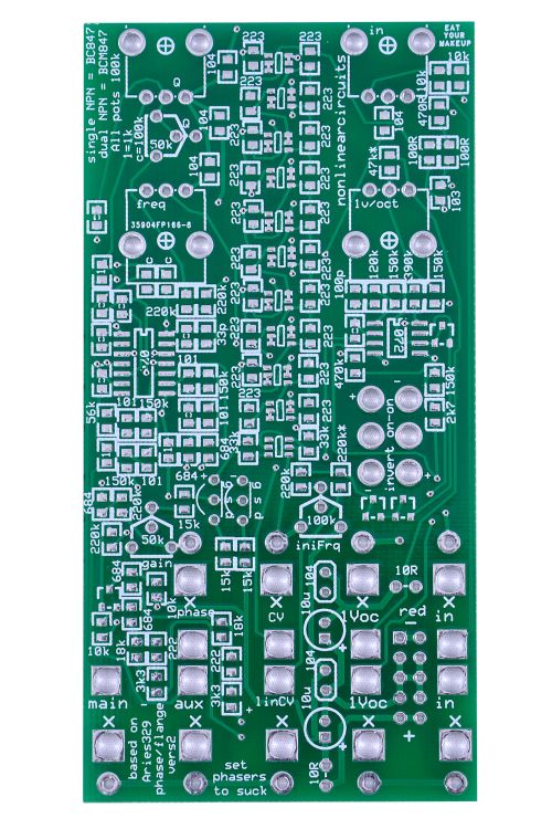
329 Phaser/Flanger - PCB | NonLinear Circuits
329 Phaser/Flanger - PCB | NonLinear Circuits
Special Price
$17.00
Regular Price
$20.00
Nonlinearcircuits 10 stage Phaser/Flanger based on the Aries 329.
This is a PCB only set in the Eurorack format.
Availability:In stock
BrandNonLinear Circuits
This module is based on the Aries 329 Phase/Flange. The main differences are in semiconductor component selection and it is all 0805 & SMD, otherwise it is pretty close to the original. The schematic for this module that can be easily found on the net has a component PD10, with 2 + terminals and 2 – terminals. Searching for this component shows a full wave bridge rectifier……hmm…. can’t be right, though reading various DIY forums shows few people were sure and there do not seem to be any online photos of the 329 PCB.
It turns out PD10 was a resin block 10 stage phase shift network available in the late 70s. The Tau pipe phaser had two and the phaser in the Arp Quadra had one. The Arp Quadra Service manual shows the internals and that is what is used in this module. Normally I would avoid any circuit requiring 11 matched NPN transistor pairs, at least since the LM394 was discontinued, but now we have the BCM847, which is cheap and matched.
"The two inputs are mixed and are both attenuated by the IN pot, as per the original Aries design.
The 1V/oct input in the upper row of jacks goes to the corresponding pot, the one in the lower row is straight thru.
CV is labelled 'Flange' on the Aries panel, but on the schematic someone has crossed off 'Flange' and written 'CV'.......really it can be used to jam a CV in to the module or as a Flange input (not a true Flange as some have pointed out). Either way a great use of this module is to have two different VCOs plugged into it,one to an input, the other into the CV/Flange input. Have the VCOs running closely together and wait for the beat frequencies.
Lin CV comes after the log circuit and injects voltage straight into the base of the phase shift network.
All the CVs connect at the base, the audio signals start at the top.
The Freq knob sets the fundamental frequency around which the circuit will operate. Basically patch in your signal and tweak the Freq knob (and Res/Q) until it sounds good.
Not sure how you are with schematics, for me it is the easiest way to grok a circuit, it is in the build manual" - Andrew (NLC)
| Brand | NonLinear Circuits |
|---|---|
| HP | 12 |
| Additional Resources | Build Guide |
Related Products
329 Phaser/Flanger - Panel | NonLinear Circuits
Special Price
$20.83
Regular Price
$24.50

